Найти Подъемник, Гидравлический разбрасыватель, Бетономешалка на Промышленность Directory, надежный производитель / поставщик / завод из Китая
Новые продукты
| Срок поставки: | 45 дней |
|---|
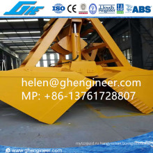
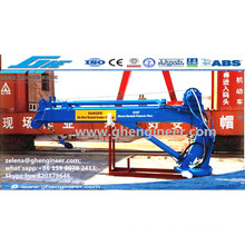
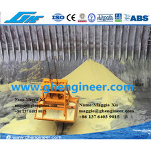
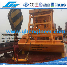
Модель: GHE-CS302


2.00 |
Technical Data |
||
2.01 |
Safe Working Load(SWL) |
Single Lift:50.0 Metric Tons(with 10% eccentric loading) Twin Lift: 32.5 x 2 Metric tons (Evenly loaded) |
|
2.02 |
Proof Load(test load) |
125% x SWL Metric Tons |
|
2.03 |
Lifting capacity of upper pad eyes |
5.5x4 metric tons |
|
2.04 |
Lifting capacity of lower pad eyes |
The spreader shall have four lasing eyes for handle damage containers. Each lasing eyes should be designed to bear vertical load of 15MT(15.0x 4Metric tons with 10% eccentric loading) |
|
2.05 |
Weight of spreader |
not more than 14.5 Metric tons |
|
2.06 |
Telescopic positions of spreaders |
20’/40’/45’ |
|
2.07 |
Twin twenty seperation |
Gap between twin twenty containers shall be adjusted from operators cabin with fully loaded containers. Standard gap:76mm, Maximum gap: not less than 1600mm |
|
2.08 |
Size of containers |
ISO IAA(0ft), ICC (20ft), & 45ft containers with ISO corner casing. |
|
2.09 |
Telescopic ranges |
20’-40’-45’ |
|
2.10 |
Telescopic speed |
From 20’ to 45’, not more than 30s |
|
2.11 |
Rotational speed of flipper arm |
For a complete travel, not more than 4s |
|
2.12 |
Rotational speed of twist locks |
For complete 90 degrees, not more than 1s |
|
2.13 |
Twin lift arm up/down |
Not more than 9s |
|
3.00 |
Hydraulic Power Unit |
||
3.01 |
mounting |
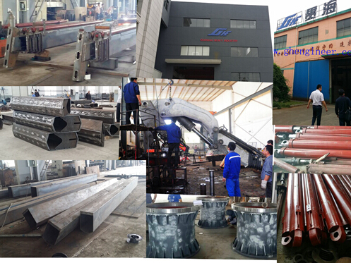
Power unit of the spreader shall be mounted on the spreader using proper vibration dampers to protect the poer unit from heavy vibrations. Oil tank should be made of stainless steel and should have a level& temperature indicators. |
|
3.02 |
Covering |
Entire power unit shall be covered by top and side covers to protect the power unit from salt laden atmosphere. Loackable side covers shall be provided for wasy access and maintenance. |
|
4.00 |
Telescopic drive system |
||
4.01 |
Telescopic |
roller chain driven by hydraulic motor |
|
4.02 |
Fine adjustment of lenghth of spreader |
Hydraulic system have flexibility to allow small changes in spreader length while handling distorted containers. Also preferable it has room to retract about 6 inch from the 20 foot position in case of jammed in cell guide. |
|
4.03 |
lubrication |
The telescopic beams should run on self lubricating sliding pads |
|
4.04 |
Shock-absording system |
Shock absorbing system should be inforperated to absob impact load and protection of the structural and mechanical components of spreader. |
|
4.05 |
Mechanical locks at 20’ 40’ 45’ positions |
There should be automatically operated mechanical locks to prevent movement of telescopic beams at 20, 40 and 45 positions. |
|
5.00 |
controls |
||
5.01 |
Spreader control |
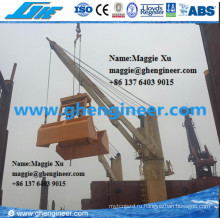
All controls of the spreader such as ON/OFF of hydraulic pump, telescoping, locking/unlocking of twist locks, up/down motion of flippers, twine twenty seperation et. Shall be remotely operated from ths operator’s cabin of the container crane |
|
5.02 |
indicators |
Facilities should be provided to indicate twist lock position, landing pin status and telescoping positions in the crane operator cab |
|
6.00 |
Spreader connections |
||
6.01 |
Attaching to the crane |
The spreader shall be connected to the pulley frame of the container crane by 04Nos. Head block twist locks. The design of attachment should be compatible with existing head block of container cranes at SLPA. |
|
7.00 |
Twist lock |
||
7.01 |
General requirement |
The twist lock of the spreader shall conform to ISO standards and e universal floating type. Iit should be controlled from the operator’s cab and should engage with the top corner casting of the containers. The floating range is 5mm in all directions |
|
7.02 |
Safe workig load each twist lock |
Shall be not less than 15MT |
|
7.03 |
Twist lock drive method |
hydraulically |
|
7.04 |
Interlock with landing pin |
Mechanical & electrical inter lock systems between the twist lock & anding pin shll be provided so that the twist locks cannot b turned either way unless the spreader lands on container |
|
7.05 |
Easy mounting and dismounting facility |
Twist locks should be incoporated with quick release system for easy removal and maintenance |
|
7.06 |
Manufatcuring drawing of twist lock |
Manufacturing drawings indicating all dimensions, heat/surface treatment required, material etc. Shall be submitted with the bid |
|
8.00 |
Guide flippers |
||
8.01 |
Guide flipper drive method |
Guide flipper acturators driven by means of hydrauli ratory acturators shall be provided. Guide flippers shall be independently controlled and be provided ay each corner of the spreader |
|
8.02 |
Mounting position |
Upper portion of the flipper arm should be at least 25mm inside the spreader outer dimensions when flippers are in “UP” positions |
|
8.03 |
Upper& lower stopper |
Upper& lower stoppers of the flippers should be made with suitable and durable shock absorbing material. |
|
9.00 |
Guide shoes |
||
9.01 |
Size &locating |
Hardened steel guide shoes of not less than 200 mm length with bevel edge shall be provided at each contact face of the twist lock post |
|


 сопутствующие товары
 FAQ Для получения дополнительной информации, пожалуйста, обращайтесь к нам! Скажите мне данные следующим образом:
 Группа Продуктов : Стропы > Другие стропы